Ultrasonic Shear Wave Scattering Characterization & Quantification
My Ph.D. work focused on characterizing and quantifying the scattering of angle-beam ultrasonic shear waves with a variety of scatterers in plates. The motivation was to obtain a deep understanding of shear wave interaction with defects and improve the reliability and accuracy of actual inspection techniques for NDE applications.
Scattering from both through-holes and notches, aimed to mimic actual ultrasonic defects in practice, is particularly meaningful to the aerospace industry because crack-like defects usually grow from fastener holes, which presents a potential hazard to the aging aircraft components if undetected.
Wavefield Visualization
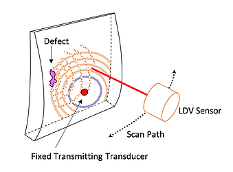
A Laser Doppler vibrometer (LDV) was used to measure the out-of-plane displacement on the surface of a single-sided mirror-finished aluminum plate caused by wave propagation resulting from a fixed ultrasonic transducer. The fiber optic sensor head was mounted on an XYZ scanner, programmed via a custom LabVIEW software, to perform point-by-point raster scans. The excitation was repeatedly generated as the scanner moved to each pixel.
Angle-Beam Inspection
“Angle-beam” means bulk waves that penetrate into a specimen at an oblique angle. Angle-beam inspection uses angle-beam probes to generate a transmitted wave propagating at a desired angle. Here, a shear-wave probe is used, which refracts primary oblique shear waves into a specimen.
There are three types of scatterers of interest. The first is a through-hole, the second is a part-through hole, and the third is a notch emanating from a through-hole.


Wavefield Data
Wavefield data, formed in a 3-D format (t, x, y), can be displayed in a wavefield video of time, which is a vivid and straightforward means to show wave propagation and scattering behavior as time progresses. Each time snapshot is a 2-D image of wave motion at a specific time.
The right video shows wavefield data, with the first one displaying a baseline wavefield without any defect and the second one the current wavefield with a 3.18 mm diameter hole at the center.
Directional Filtering
The aim of directional filtering is to extract waves propagating with a specified range of directions.
The general idea is to construct a 2-D directional kx-ky filter, multiply it with the wavefield data in the Fourier domain, and reconstruct the filtered directional waves in the time-space domain via the inverse Fourier transform.
The right video shows an example of before and after separating and extracting forward-propagating waves from the total wavefield. The direction range of forward-propagating waves is from 0 to 180 degrees, corresponding to the Fourier data where ky is positive.
More Examples
Directional filters can be built with any propagation direction range. The right figure shows more examples of directional filters with various propagation directions and their respective filtered wavefield snapshots at 18.6 μs.
As can be seen from the figure, directional filtering is effective and robust to decompose wavefields by propagation directions.

Wavefield Baseline Subtraction
The objective of wavefield baseline subtraction (WBS) is to isolate differences between baseline and current wavefields, which are recorded before and after a change (e.g., damage) is introduced.
For the sake of compensating for temporal and spatial misalignment, baseline alignment, which aims to find a baseline that is well-aligned to the current wavefield, is developed to improve the performance of WBS.
The right upper figure shows a time snapshot of current, unaligned baseline, and residual wavefields after direct WBS at 13 μs. As can be seen from the figure, incident waves are not fully removed before hitting the hole. Consequently, direct WBS is usually not effective to remove incident waves and isolate scattered waves.
The right lower video shows the current, aligned baseline, and residual wavefields after applying the WBS procedures. As can be seen from the residual wavefield, only a slight amount of incident waves remains and hole-scattered waves are dominant.

Phase-Velocity Filtering
Phase velocity filtering, as its name implies, is aimed to separate wave modes by their respective phase velocity ranges. Here, phase velocity filters are developed in the frequency-wavenumber domain for isolating and separating Rayleigh, shear, and longitudinal waves.
The right video shows an example of before and after phase velocity filtering of each wave mode. As can be seen from the video, phase velocity filtering is helpful to separate wave modes.
Ray Tracing
The goal of ray tracing analysis is to simulate how incident rays of shear waves propagate and how the subsequent scattered rays are affected by various scatterers.
The upper video shows an example of tracking incident shear waves in pristine plates without any damage. As can be seen from the video, the calculated wave trajectories of incident shear wave skips, the 1st skip in red, 2nd skip in green, and 3rd skip in blue, are in good agreement with the actual data.
The lower video shows an example of hole-scattered shear waves in red resulting from the 2nd incident shear wave skip in green. As can be seen from the video, these calculated trajectories are in excellent agreement with the experimental wavefronts as time progresses, which validates the accuracy of the ray tracing process.

Time-Space Windowing
The purpose of time-space windowing is to extract the waves of interest in the time-space domain.
Thanks to ray tracing analysis, the calculated wave trajectory can be enlarged to a time-space filter, which is constructed by setting a ring width to broaden the calculated wave trajectory to an arc-like curve that fully encloses the wanted waves.
The gallery below presents some examples of filtering in hole-scattered waves and notch-scattered waves.
Note: For the third video of tracking notch-scattered waves, time-space filters are built based on a point-scattering approximation rather than an exact ray tracing analysis.


Incident Wave Subtraction
The purpose of incident wave subtraction is to remove incident waves by utilizing the current wavefield itself instead of applying WBS. This tech- nique is customized particularly for the scattering analysis of compound scatterers (e.g., hole+notch).
The general idea is to combine directional filtering and spatial windowing as introduced previously to remove incident waves without using the baseline.
The upper video presents how to remove the 3rd incident skip by removing all incident shear wave skips before hitting the hole (spatially below the hole lower edge).
The lower video explains how to remove the 3rd incident shear wave skip after hitting the hole (spatially above the hole lower edge), which spatially overlaps with the notch-scattered waves.
Scattering Quantification
The gallery below presents some quantification results of through-hole scattering, part-through-hole scattering, and notch scattering. Here, all the scattering is quantified as a plot of scattered energy versus polar angle relative to the hole center.


